The resistance of the fluid is responsible for the energy loss (ie drag loss). One is the resistance loss along the way caused by the viscosity and inertia of the fluid; the other is the local resistance caused by the blockage and disturbance of the solid wall to the fluid due to the sudden expansion or contraction of the pipeline interface. loss. The liquid resistance loss is usually expressed by the energy loss (or head loss) h1 of the fluid per unit weight, and the gas is usually expressed by the energy loss (or pressure loss) of the fluid per unit volume > p1.
(1) Resistance along the way and resistance loss along the way.
(2) Local resistance and local resistance loss.
(3) Laminar flow resistance and turbulent flow resistance change, showing irregularities, but the entire fluid still moves along the mainstream direction. In a circular tube, the flow state of the fluid is related to the average velocity v and the tube diameter d kinematic viscosity coefficient. Combining the above three parameters into a dimensionless number is called the Reynolds number and is represented by Re. Experiments have shown that the critical Reynolds number is about 20000. When the Reynolds number is greater than 2000, the flow state is turbulent; when the Reynolds number is less than 2000, it is laminar flow. Turbulent flow resistance is much greater than laminar flow resistance.
(4) The total loss of fluid energy According to long-term practical experience, the calculation problem of energy loss is transformed into the problem of finding the drag coefficient. The energy loss is written in the form of multiples of the flow velocity and head. When the energy equation is listed, it can be combined with the flow velocity and head into one item for easy calculation. Due to the complexity of the influencing factors, the two dimensionless coefficients input and string in the formula must be obtained by analyzing some typical experimental results and using empirical or semi-empirical methods. Total loss of fluid energy: The total loss of fluid energy is equal to the sum of the along-course loss of each pipe section and the sum of each local loss.
(5) Measures to reduce resistance: reduce the roughness of the pipe wall and replace the rigid side wall with a flexible side wall; prevent or delay the separation of the fluid and the wall, avoid the generation of the vortex area or reduce the size and strength of the vortex area. Measures to reduce resistance for
steel pipe fittings: Generally, for elbows with small diameter d, the radius of curvature ruler can be used reasonably to reduce resistance. Ventilation elbows with large cross-sections need to be installed with reasonable deflectors to reduce local pressure. drag effect. For reducers with varying pipe sections, a certain length of reducer or expander should be used. Three-way or four-way can be provided with diversion partitions. A very small amount of additives are added inside the fluid to affect the internal structure of the fluid movement to achieve drag reduction.
(6) Reduce the energy loss of pumps and fans: The energy loss of pumps and fans is usually divided into three categories, namely hydraulic loss, volume loss, and mechanical loss. Hydraulic loss: The size is closely related to the geometric shape of the flow parts, the roughness of the wall, and the viscosity of the fluid. Hydraulic losses include inlet losses, impact losses, hydraulic losses in the impeller, dynamic pressure conversion, and casing outlet losses.
 Threeway Steel is known as a professional supplier engaged in manufacturing and distributing a wide range of steel pipe, and our headquarter located the central part of China – Hunan and six associated factories throughout China.
 Threeway Steel is known as a professional supplier engaged in designing, manufacturing and distribution of a wide range of steel products with the headquarter located the central part of China – Hunan and six associated factories throughout China.
 Threeway Steel is known as a professional supplier engaged in designing, manufacturing and distribution of a wide range of steel products with the headquarter located the central part of China – Hunan and six associated factories throughout China.
 Threeway Steel is known as a professional supplier engaged in designing, manufacturing and distribution of a wide range of steel products with the headquarter located the central part of China – Hunan and six associated factories throughout China.
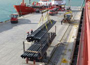 Threeway Steel is known as a professional supplier engaged in designing, manufacturing and distribution of a wide range of steel products with the headquarter located the central part of China – Hunan and six associated factories throughout China.

